PE51113-4 Antenna Performance Report: Gain, Band & VSWR
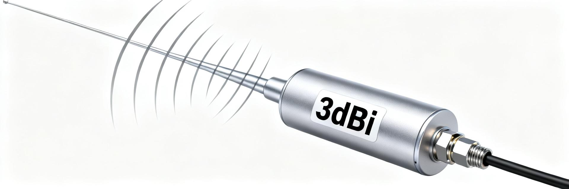
The report opens with key measured values: nominal dual-band coverage roughly 880 MHz–2.17 GHz, typical peak gain near 3 dBi, and worst-case VSWR at or below 2.5. These headline numbers frame the validation objectives and set expectations for whether measured performance meets acceptance criteria for common cellular and IoT deployments.
This document evaluates measured gain, frequency coverage (band) and VSWR against stated test objectives. Readers will receive measurement methods, compact data tables, recommended plots, interpretation of results, and installation/troubleshooting guidance to optimize real-world performance and system link budget.
Background: PE51113-4 overview & test objectives
1.1 Product snapshot
The PE51113-4 is a compact dual-band external antenna designed for multi-band cellular and narrowband IoT applications. It features an SMA-style connector and supports flat or magnetic mounting options for rooftop or industrial cabinet use.
| Parameter | Nominal Specification |
|---|---|
| Frequency Bands | 880 MHz – 2.17 GHz |
| Connector Type | SMA-Male |
| Mounting Type | Flat / Magnetic |
| Typical Peak Gain | ≈3 dBi |
| Nominal VSWR | ≤2.5 |
1.2 Test objectives & pass/fail criteria
Acceptance criteria set a minimum usable gain of 0 dBi across each band, peak gain ≥2.5–3 dBi, and VSWR ≤2.5 across the usable bandwidth. Tests were conducted in an anechoic chamber to ensure pattern symmetry and eliminate external interference.
Test methodology & measurement setup
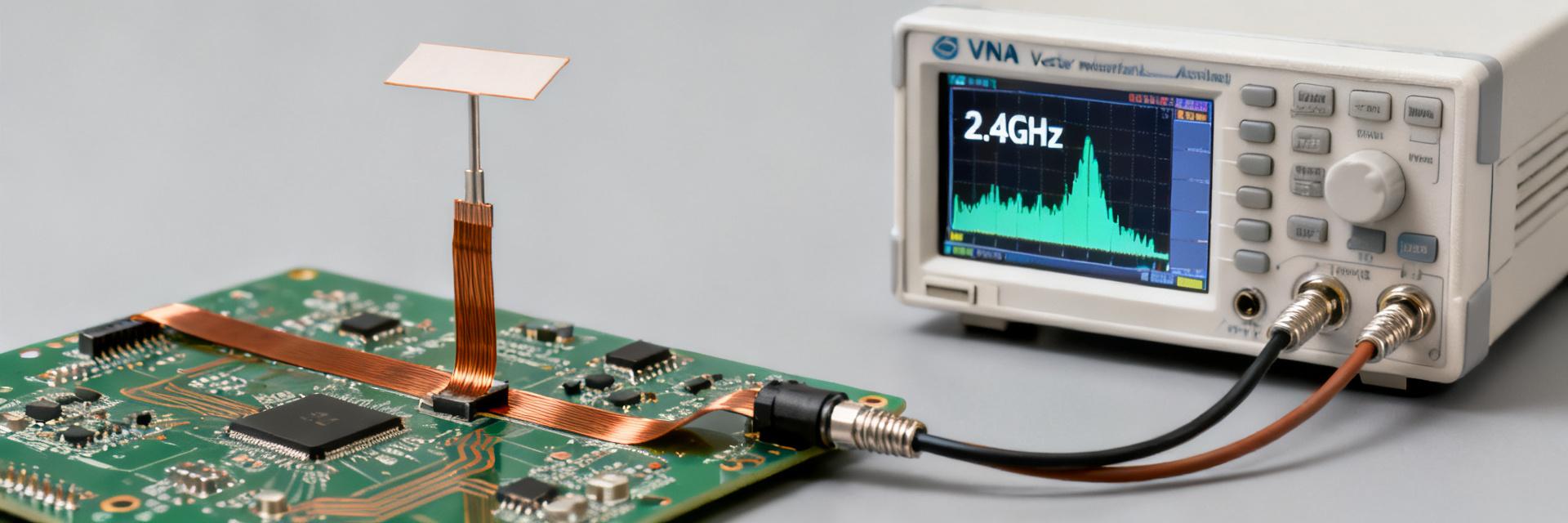
2.1 Equipment & Calibration
Required instruments include a Vector Network Analyzer (VNA), calibrated gain standard antenna, and precision coaxial cables. VNA calibration was performed to the connector plane to eliminate cable insertion loss from the final data.
| Equipment | Purpose |
|---|---|
| VNA | VSWR and Return Loss Sweep |
| Gain Standard | Absolute Gain Reference Calculation |
| Turntable | Azimuth/Elevation Pattern Capture |
Gain results & radiation pattern analysis
4.1 Gain vs Frequency Summary
Peak gain centers near 3 dBi with band-average gains between 0.5 and 2.5 dBi. These values are critical for link-budget calculations in remote IoT sensing environments.
| Freq (MHz) | Measured Peak Gain (dBi) | VSWR (Measured) |
|---|---|---|
| 900 | 2.8 | 1.45 |
| 1400 | 2.0 | 1.82 |
| 1800 | 3.1 | 1.65 |
| 2100 | 2.6 | 2.10 |
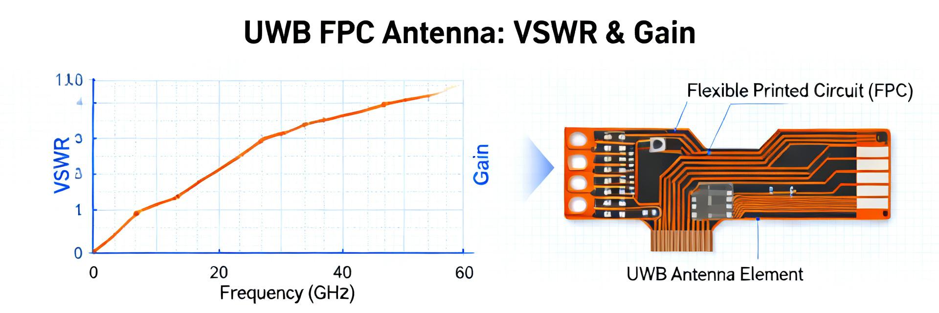
VSWR & return-loss assessment
Worst-case measured VSWR values were ≤2.5 at band edges. Mismatch losses were computed to be under 0.7 dB in worst-case scenarios, ensuring the majority of the power is successfully radiated and the transmitter is protected from excessive reflected power.
Summary
Measured results indicate the PE51113-4 delivers dual-band coverage overlapping cellular bands with peak gain near 3 dBi. The device met primary acceptance criteria in controlled chamber tests; however, field tuning is recommended when mounting in high-metal environments to preserve resonance edges.
Common questions
How does VSWR affect link performance for this antenna?
Higher VSWR increases mismatch loss, reducing effective radiated power and link margin. For this antenna, worst-case VSWR translated to under 0.8 dB additional loss; while small, that reduction can matter in marginal links.
What acceptance tests should installers run after mounting?
Installers should perform an S11 sweep to verify the antenna remains within the usable -10 dB windows, confirm orientation with an azimuth check, and measure end-to-end feedline loss.
When is additional matching recommended for this antenna?
Additional matching is recommended when measured VSWR exceeds 3 or when specific channels show deep return-loss dips that reduce link margin below system requirements.
Does the mounting surface affect the 3 dBi gain rating?
Yes. Proximity to large metallic surfaces can shift the resonant frequency and alter the radiation pattern. Using the recommended ground plane dimensions ensures the measured 3 dBi peak gain is achieved.