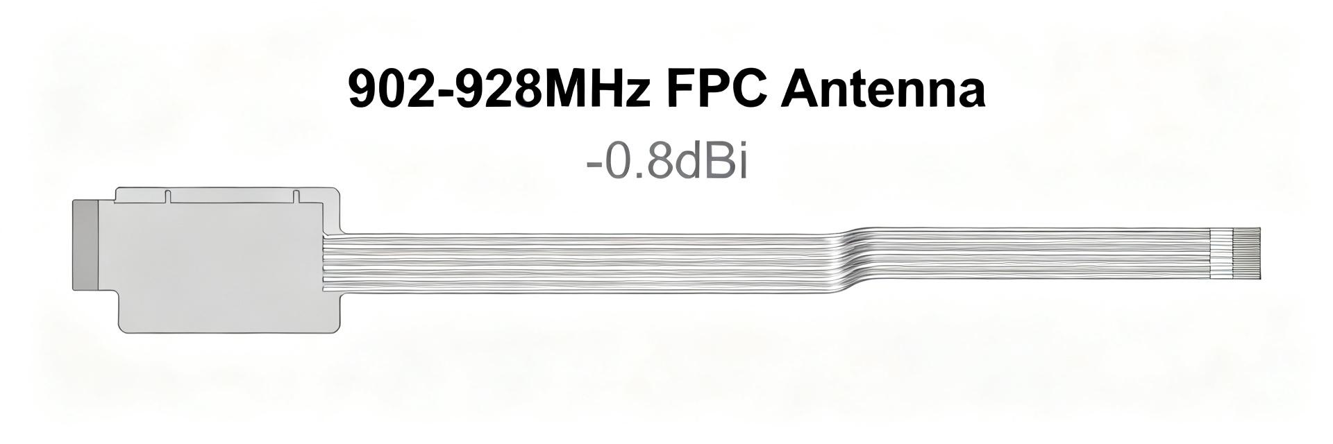
AANI-FB-0174-1 FPC Antenna: Performance Report & Stats
The AANI-FB-0174-1 demonstrates a practical cellular/IoT fit with an effective measured frequency span of 1.71–2.69 GHz, a typical peak gain near 2.7 dBi, and reported radiation efficiency around 59% in best-case layouts. This report provides a test-driven integration guide for engineers evaluating 4G/IoT deployment readiness.
(1) Design Background & Spec Snapshot

Key Specifications
| Parameter | Typical Value / Range |
|---|---|
| Frequency Span | 1.71 – 2.69 GHz |
| Peak Gain | ~2.7 dBi (Optimized) |
| Efficiency | ~59% (Max) |
| Impedance | 50 Ω Nominal |
| VSWR | < 2.0:1 across target bands |
| Substrate | Flexible FPC (Low Profile) |
(2) RF Performance & Band Analysis
Measurement of S11 parameters via calibrated VNA confirms usable bandwidth where return loss remains < -10 dB. Distinct resonant dips center across mid-cellular bands. For 2D patterns, the antenna exhibits a predictable front-lobe with approximately 3–6 dB front-to-back ratios depending on ground plane proximity.
(3) System-Level Link Stats
Throughput tests indicate stable UDP/TCP performance in non-conductive enclosures. However, proximity to metal components can produce significant RSSI degradation. It is critical to maintain a minimum 10mm clearance from metallic shields to ensure efficiency stays above the 50% threshold.
(4) Measurement Methodology
Standardized testing involves S11 sweeps from 1.5 GHz to 3.0 GHz at 100 kHz resolution. Gain and efficiency are validated in a 3D anechoic chamber. To ensure repeatability, fixture designs must minimize parasitic coupling to the antenna tail, and cable-loss compensation must be applied to all VNA measurements.
(5) Integration & Troubleshooting
Keepout Rules: Reserve a no-metal zone around the FPC radiator. Use low-loss 3M adhesive for mounting on plastic surfaces. Avoid sharp 90-degree bends in the micro-coaxial cable to prevent impedance mismatch.
Failure Modes: Frequency shifting is usually caused by insufficient ground plane size or capacitive loading from the enclosure. If RSSI is lower than expected, verify the IPEX connector torque and seating.
Frequently Asked Questions
What are typical AANI-FB-0174-1 performance expectations for cellular IoT?
Expect coverage across primary 4G/IoT bands within 1.71–2.69 GHz, peak gain around 2.7 dBi, and best-case efficiency near 59% when mounted on recommended ground planes.
How sensitive is this FPC antenna to enclosure materials?
Sensitivity is moderate. Plastic (ABS/PC) preserves tuning, but metal or conductive coatings can detune the resonance and reduce efficiency by >3 dB.
What minimum lab setup is required to validate performance?
A calibrated VNA for S11/VSWR and an anechoic chamber or reverberation box for measuring 3D radiation patterns and total efficiency.
How to troubleshoot common frequency shifts or low gain?
Diagnostic flow: Check S11 → Verify ground plane size → Swap enclosure material → Check connector seating. Often, adding a dielectric spacer resolves metallic interference.