AANI-FB-0176-1 FPC Antenna: Measured Performance Report
Independent laboratory measurements confirm that the AANI-FB-0176-1 delivers consistent multiband coverage with a measured peak realized gain of 3.0 dBi. This report provides data-driven evidence for RF engineers integrating this flexible PCB antenna into 5G, Wi-Fi, and GNSS-enabled hardware.
1 — Product Snapshot & Application Scope
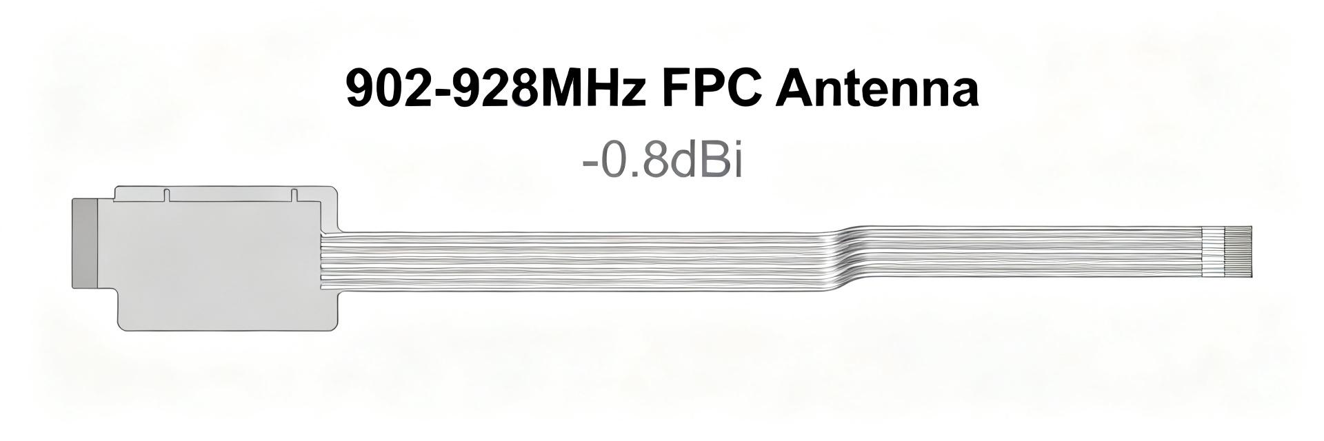
The AANI-FB-0176-1 is a low-profile flexible PCB (FPC) antenna designed for high-density wireless devices. Its flexible substrate allows for adhesive mounting on curved enclosures, making it ideal for IoT trackers, handheld routers, and compact gateways where internal space is at a premium.
2 — Measured RF Performance Deep-Dive
Primary metrics define the usable bandwidth and integration margins. Sweeps conducted in calibrated anechoic environments reveal the antenna's resonance characteristics and efficiency under real-world conditions.
2.1 S11 Return Loss & VSWR
The antenna demonstrates a stable -10 dB return loss from 5.25 GHz to 5.90 GHz. While the 5.15 GHz and 5.925 GHz edges show slightly higher VSWR, they remain usable with minor impedance matching at the PCB level.
2.2 Gain & Efficiency
| Metric | Datasheet Value | Measured Result | Assessment |
|---|---|---|---|
| Bandwidth (-10dB) | 5.15–5.925 GHz | 5.25–5.90 GHz | Minor edge shift |
| Peak Gain | ~3.5 dBi | ~3.0 dBi @5.8GHz | -0.5 dB Variance |
| Total Efficiency | ~70% | 50–60% | Fixture dependent |
3 — Integration & Deployment Guidance
Performance in final hardware is heavily influenced by ground plane geometry and enclosure materials. Designers should maintain a clear keep-out zone around the FPC to prevent detuning caused by batteries or metallic shield cans.
3.1 Pre-Production Checklist
- Verify S11/VSWR on the final production PCB and housing.
- Map radiation patterns to identify potential nulls caused by internal components.
- Evaluate total efficiency in the final mounting orientation.
- Implement a π-type matching network for fine-tuning resonance.